PCB Design

Cansat Flight Computer PCB.

Custom flight computer designed for reliable system integration and rapid debugging.

3D render of the Cansat Flight Computer PCB.

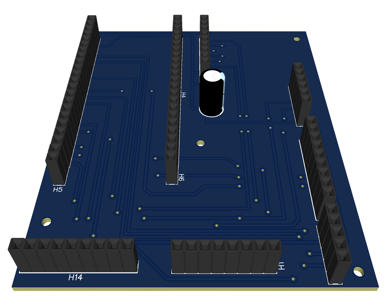
This PCB was developed as the main flight computer for our Cansat project, a soda-can-sized satellite designed for environmental sensing and telemetry. The project was built for the CanSat International Competition organized by UNAM in Mexico.

The board was built around a practical engineering philosophy: simplify integration, reduce wiring complexity, and make debugging as straightforward as possible. Plug-and-play connectors, clearly organized interfaces, and accessible test points allowed the team to validate subsystems quickly and isolate issues during development.

By consolidating sensors, communications, and power distribution into a single board, the PCB provided a reliable platform for testing and system integration throughout the project.

How It Works

Engineering notes.

The CanSat needed several electronics subsystems to fit and work together inside a very small physical volume. Sensors, telemetry hardware, power connections, and debugging access all had to be organized without turning the payload into a fragile bundle of loose wiring.

Early subsystem work relied on separated modules and jumper-heavy connections, which made assembly, debugging, and validation slower than they needed to be. A dedicated flight computer PCB gave the system a cleaner integration platform with predictable interfaces and fewer wiring-related failure points.

The ESP32 acted as the central controller for the flight computer. The TMP117 provided temperature measurements, the DPS310 provided pressure data for altitude-related telemetry, the LSM9DS1 supplied inertial data, and the RFM69HCW handled radio telemetry to the ground station.

The PCB was organized around readable connector groups, power distribution, sensor interfaces, and debugging accessibility. The goal was not only to make the system compact, but to make it serviceable during subsystem bring-up and full mission integration.

TMP117 DPS310 LSM9DS1
ESP32 Flight Computer
RFM69HCW Radio Telemetry
Ground Station Dashboard

The design started from system requirements and interface planning: which signals needed to leave the board, which modules needed dedicated connectors, and which points had to remain accessible during testing.

From there, the work moved through schematic capture, connector selection, board placement, routing, and design-for-debug decisions. The layout prioritized signal organization and serviceability so the board could be read, probed, and modified during development instead of only being packed as tightly as possible.

  • Grouped sensor, communication, and power interfaces by function.
  • Reduced loose wiring by consolidating subsystem connections onto one board.
  • Kept debugging and subsystem access in mind during connector placement.

Verification followed a staged bring-up process. The board was first checked for continuity and power integrity, then individual interfaces were validated before moving into integrated subsystem testing.

During system-level testing, the ground station dashboard was used to observe telemetry receive status, temperature, pressure, altitude, descent velocity, mission phase, and mission state. This made it easier to confirm that the flight computer was not only powering up, but also producing useful mission data.

The simulator below reflects the competition profile: the original target altitude was 400 m, but the flight ceiling was changed to 315 m shortly before the mission.

Ground station dashboard used during Cansat telemetry testing.

The prototype served as a functional central flight computer for subsystem testing and system integration. It reduced wiring complexity, made debugging more direct, and provided a cleaner platform for testing sensing, telemetry, and mission-state behavior.

During the competition mission, the PCB worked as expected and was able to transmit data throughout the full flight with minimal packet loss. The board also survived landing with no electrical damage. Our team placed 14th out of the 43 teams that participated in the final competition and 14th out of the 150 teams that participated across the full CanSat International Competition organized by UNAM in Mexico.

One improvement area was the image telemetry path: seven packets were lost while sending the required anaglyph picture. Future revisions would improve silkscreen labeling, add more dedicated test points, refine layout details, and include clearer revision-specific documentation so bring-up and handoff are even easier.

Interactive Demo

Mission simulator.

A lightweight simulation of the flight computer telemetry path during a CanSat mission profile.

Mission Control

CanSat telemetry loop

Start the sequence to see the ESP32 collect sensor data and push live telemetry to the ground station through the radio link.

Drone ascent / release point
400 m 200 m 0 m
Mission Phase Idle
Altitude 0 m
Descent Velocity 0.0 m/s
Temperature 24.0 °C
Pressure 1013.3 hPa
Telemetry Link Standby
Last Packet --