ASIC

Similarity Detector ASIC.

Hardware-accelerated vector similarity detection implemented through a full-custom ASIC design flow.

Core layout view of the Similarity Detector ASIC. Core layout view of the Similarity Detector ASIC.

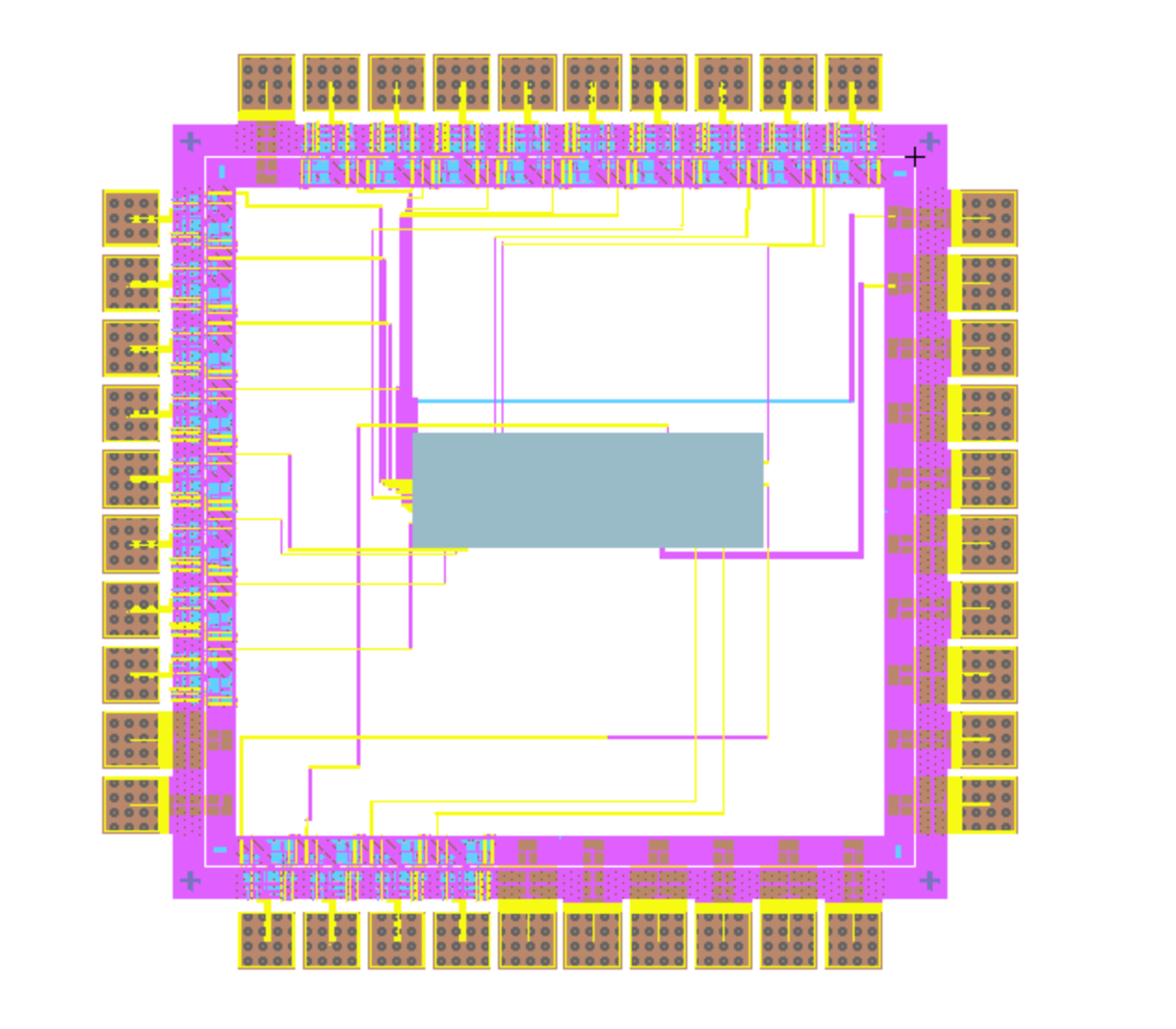
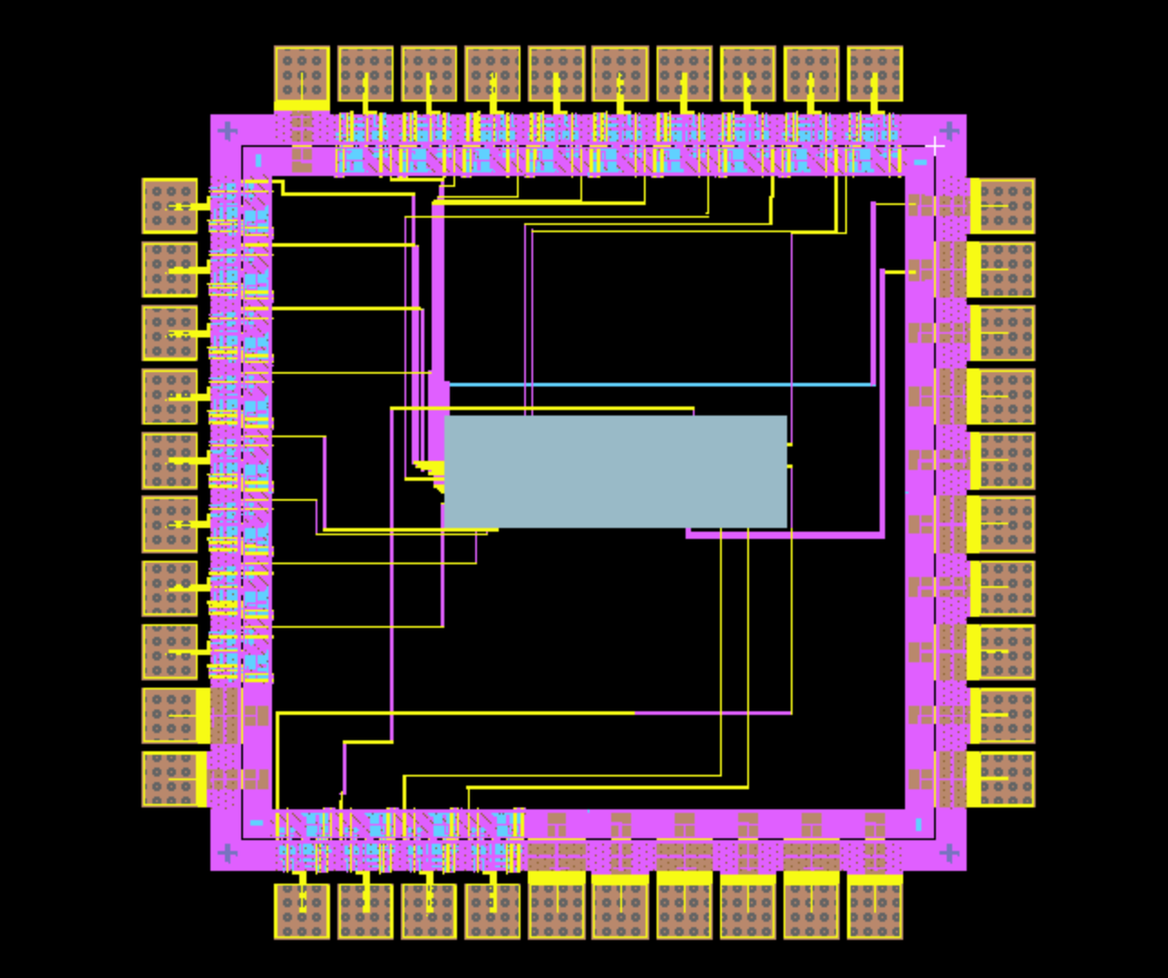
The Similarity Detector was developed as the final project for an Integrated Circuits Design course and implements a custom ASIC using a full-custom VLSI design flow.

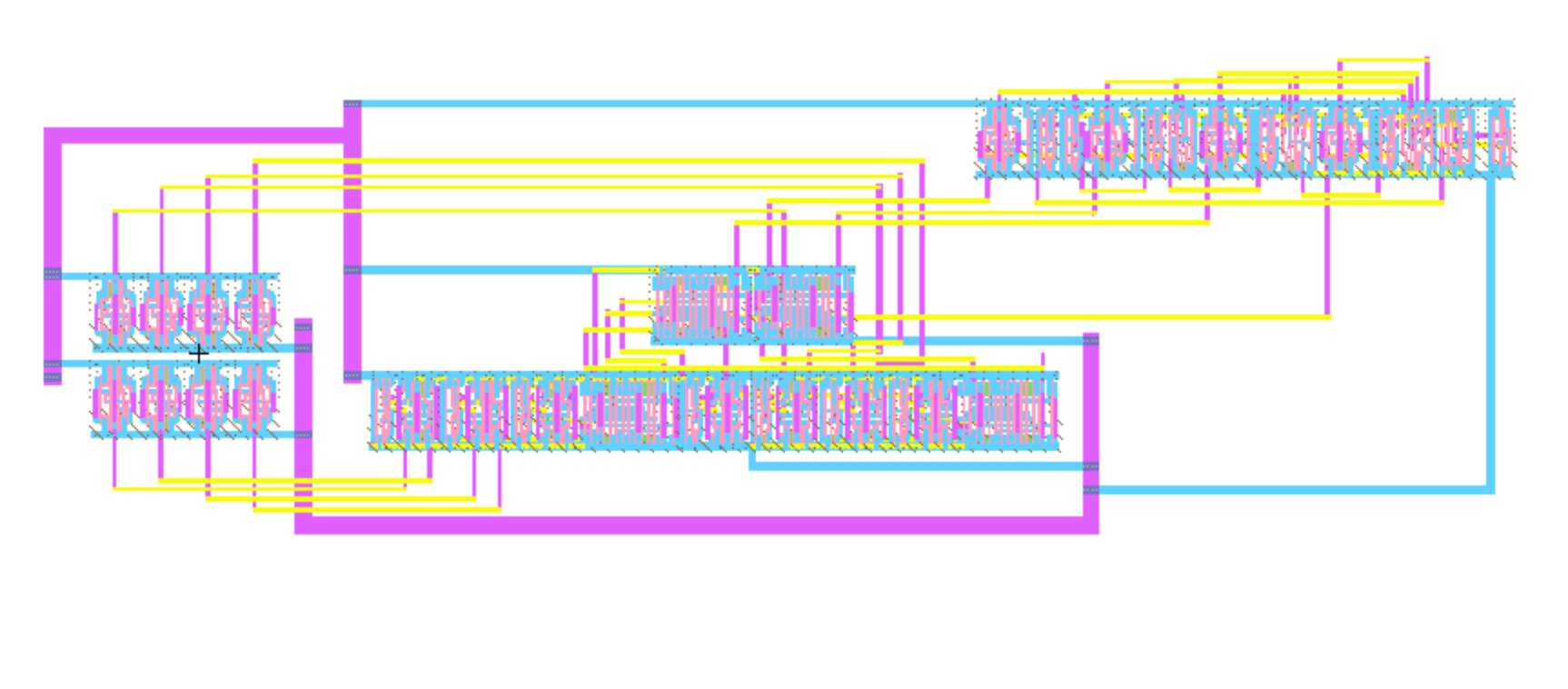
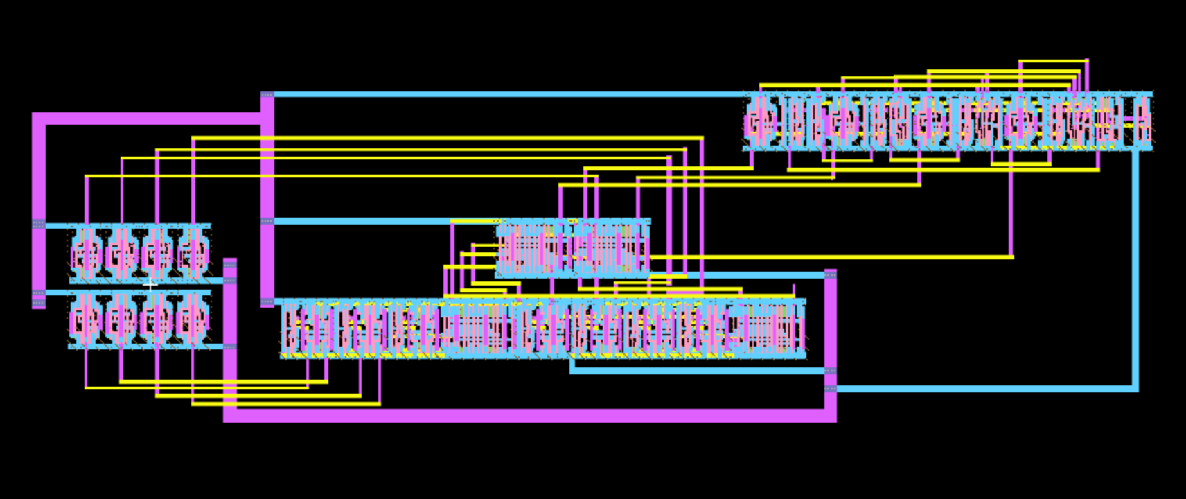
The circuit compares two 8-bit input vectors and determines whether their similarity exceeds a programmable threshold. Internally, the design performs bitwise XNOR operations to identify matching bits, counts the total number of matches, and compares the result against a user-defined threshold.

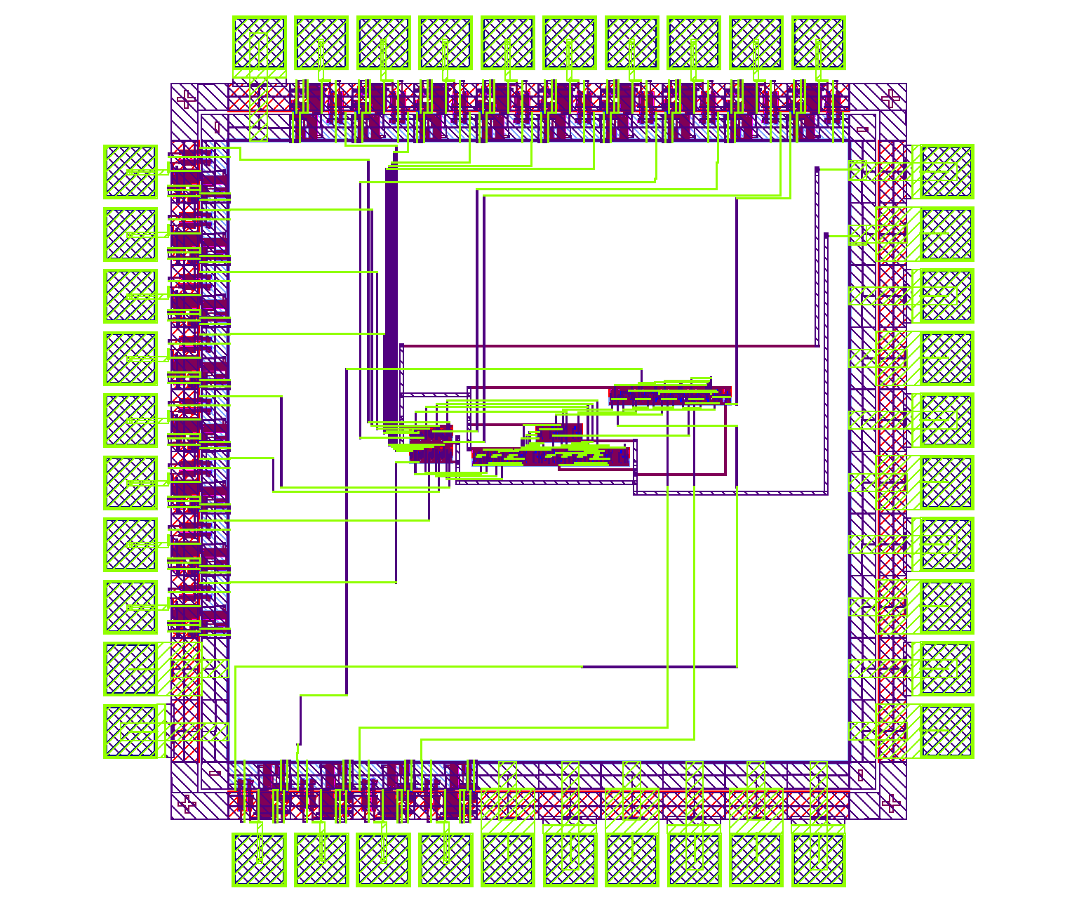
The project was implemented from transistor-level schematics through physical layout and verification using Electric VLSI. Functional validation was performed through simulation and testbench development to ensure correct operation across multiple comparison scenarios.

This design demonstrates how specialized hardware can accelerate decision-making tasks by performing comparisons directly in silicon.

How It Works

Engineering notes.

Comparing two binary vectors directly in hardware is useful when a system needs to make fast similarity decisions without relying on software execution.

Instead of sending data to a processor, the circuit performs the comparison entirely in combinational hardware, allowing similarity evaluation in a single logic path.

This ASIC compares two 8-bit input vectors and determines whether the number of matching bits meets or exceeds a programmable threshold.

The Similarity Detector is organized as a simple hardware pipeline.

XNOR8 to match counter to threshold comparator block diagram x[7:0] w[7:0] XNOR8 Bitwise Compare match[7:0] match_counter8 Match Count count[3:0] comp4_ge Threshold Compare b[3:0] out

Each pair of bits from x[7:0] and w[7:0] is compared using XNOR logic. Matching bits produce a logic 1 while mismatches produce a logic 0.

The match_counter8 block counts the total number of matching bits and generates a 4-bit count value. The comp4_ge comparator then checks whether matches >= threshold. If true, the output is asserted.

Example Operation

x = 10110110
w = 10100111

XNOR result = 11100110

Matches = 6
Threshold = 5

Output = 1

The design was divided into reusable digital blocks:

  1. XNOR8
  2. Match Counter
  3. Threshold Comparator

Each block was first developed and verified independently before integration into the top-level design.

After schematic construction, every module was translated into transistor-level CMOS layout using Electric VLSI. The physical implementation followed the same hierarchy used in the schematic design to simplify verification and debugging.

Once the core was validated, a complete chip-level layout was assembled with padframe integration, power routing, ground distribution, and external I/O connections.

Functional verification was performed through switch-level simulation using IRSIM.

Test cases included:

  • Perfect matches
  • Partial matches
  • No-match conditions
  • Threshold boundary cases
  • Minimum threshold values
  • Maximum threshold values
matches = popcount(x XNOR w)
output = matches >= threshold

Physical verification included DRC, ERC, and NCC to ensure consistency between schematic and layout implementations.

The final ASIC successfully evaluates similarity between two 8-bit vectors and generates a binary decision based on a programmable threshold.

The project demonstrated the complete custom IC design flow, including architecture development, transistor-level schematics, physical layout, padframe integration, simulation, and verification.

Beyond the functional result, the project provided hands-on experience with hierarchical VLSI design, physical routing challenges, and the verification process required to transform a digital concept into a manufacturable integrated circuit.

Interactive Demo

Vector similarity logic.

x[7:0]

w[7:0]

XNOR 00000000
Match Count 0
Output 0